This 1965 MIT Science Reporter television program serves as a remarkable time capsule, capturing a pivotal moment in the history of space exploration and computer technology. Presented by MIT in association with WGBH-TV Boston and produced for NASA, the program provides an in-depth look at the Apollo guidance computer and navigation equipment, a technological marvel weighing less than 60 pounds (27 kg) but tasked with guiding astronauts to the Moon and back.
Hosted by MIT reporter John Fitch, the program features key scientists and engineers including Eldon Hall, Ramon Alonzo, and Albert Hopkins from the MIT Instrumentation Laboratory, as well as Jack Poundstone from Raytheon’s Space Division. Together, they delve into the intricate complexities and monumental challenges of the project, from spacecraft trajectory control to computer construction and onboard telescope operation.
This historical broadcast, published by the “From the Vault of MIT” channel, focuses on the miniaturized, yet profoundly capable, Apollo guidance computer, a machine that had to perform under the most stressful and unforgiving conditions. Fitted with microcircuits and memory cores, this piece of engineering was designed to offer unprecedented computational power within an incredibly constrained weight budget.
As emphasized by Eldon Hall (1923-2022, the leader of hardware design efforts for the Apollo Guidance Computer [AGC] at MIT), Ramon Alonso, and others, the Apollo Guidance Computer was not just an exercise in technical ingenuity; it was a solution to a series of almost insurmountable challenges, including safely guiding a spacecraft hundreds of thousands of miles away from Earth and back. The program sheds light on the sheer depth of scientific research and technological innovation that went into the Apollo missions, ultimately broadening our understanding of both space travel and the monumental role of computing in achieving it.
Video: MIT Science Reporter – “Computer for Apollo” [Apollo Guidance Computer] (1965)
The Apollo Missions’ Silent Hero: The Apollo Guidance Computer
The video begins with test engineers examining an intricate assembly of telescopes, gyroscopes, and electronic components that make up the guidance and navigation system for Project Apollo. This system is designed to assist astronauts during their mission to the Moon and back. The focus of the video is on the miniaturized computer that serves as the core of this guidance system, which is the subject of discussion in the episode of “MIT Science Reporter.”
Navigating the Complexities of Space
In the second part of the video, John Fitch, the MIT Science Reporter, introduces the setting as the MIT Instrumentation Laboratory, which is responsible for designing the guidance and navigation system for the Apollo spacecraft. Fitch reflects on how navigational challenges have evolved over time. In the past, humans relied on natural landmarks like the rising sun or winding rivers to find their way.
Later on, the quadrant and magnetic compass guided explorers even when familiar landmarks were out of sight. In the context of the Apollo mission, Fitch describes the immense complexity of navigating through a million miles of empty space, where traditional directional markers like north, south, or even up and down are irrelevant. The task involves a plethora of measurements and millions of calculations. He refers to an Apollo flight plan to explain that there are several critical maneuvers required for the mission’s success.
For example, after reaching Earth’s orbit, the spacecraft must be precisely injected into a trans-lunar trajectory at a specific point in space and time. Fitch likens this to aiming at a moving target from a revolving platform on a moving train that’s going around a curve. He adds that midway through the mission, the programmed course must be evaluated for errors, and potential mid-course corrections have to be made. Similar complex maneuvers are needed throughout the mission.
To delve deeper into the workings of the guidance and navigation system capable of managing these complexities, Fitch mentions that he talked with Eldon Hall, the Deputy Associate Director of the Instrumentation Lab.
Eldon Hall elaborates on the components of the Apollo guidance and navigation system, which consists of two key measurement elements, a computer, and a computer display and control unit. The inertial measurement unit, another crucial part, contains gyroscopes and accelerometers that measure the spacecraft’s angles and velocity. The system also includes a sextant, similar to what sailors use for earthly navigation.
John Fitch inquires about the challenges Hall’s team has to solve. Hall explains that the most basic issue is determining the spacecraft’s position at any given time. To do this, angles are measured between a point on Earth and a star. As the spacecraft moves away from Earth, this angle narrows, which helps in calculating the distance between the Earth and the spacecraft. The astronaut uses the sextant to first position the spacecraft so that a terrestrial landmark is visible and then adjusts the sextant to superimpose a star on that landmark.

Fitch asks what kinds of landmarks the astronaut might see, to which Hall responds that it could be San Francisco Bay, the Great Lakes, Cuba, or Cape Cod. Mirrors inside the sextant help in superimposing the star over the selected landmark.
Fitch then questions how the angle is actually measured. Hall explains that the computer automates this process. The astronaut must first identify the star and the landmark to the computer. As the astronaut positions the spacecraft and sextant, the computer measures the angles between the landmark and the star. Once the astronaut confirms that the star is correctly superimposed, they push a ‘mark’ button, signaling the computer to record the angles and time of measurement, which it uses to calculate the spacecraft’s position in space.
John Fitch asks what can be done if the spacecraft’s position is found to be incorrect. Eldon Hall responds that the computer has the capability to reposition the spacecraft by turning on the motors to steer it, and then shutting them off when the correct position is reached. Fitch clarifies if this means the spacecraft will then coast on a new, corrected path, to which Hall confirms that it does.

Apollo Guidance and Navigation Systems test laboratory
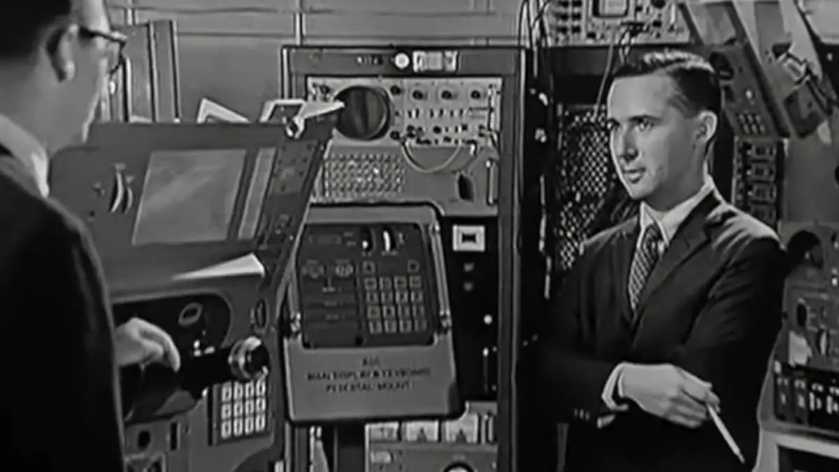
In this segment, John Fitch speaks with Ramon Alonso, the Assistant Director of the Instrumentation Laboratory, about the Apollo guidance and navigation system’s operations. Alonso focuses on how astronauts control the guidance equipment through a computer, which is operated via a display and keyboard. Two instances of this display and keyboard are available: one in the lower equipment bay with the rest of the navigation equipment, and another near the astronauts’ couches for convenience.
The system uses a relatively simple coding scheme involving numeric verbs and nouns, essentially forming ‘little sentences made of numbers.’ Alonso demonstrates this by using the verb “16” for “continuous display in decimal” and the noun for “time.” By pressing ‘Enter,’ the computer displays the time since launch in both hours and seconds.

Fitch comments that such detailed time-keeping would be particularly useful around the time of the spacecraft’s launch, to which Alonso agrees. The computer will continue to display this information until told otherwise through another numeric command, or verb.
Alonso also gives an example of how the computer can control the spacecraft’s optics or telescope. By invoking a verb for ‘point’ and a noun for ‘optics,’ the computer requests the specific angle to which the optics should be pointed. This is confirmed through a sequence of numeric inputs by the operator.
Fitch notices that the numbers on the display start flashing, indicating that action is required from the operator. Alonso confirms this, explaining that the flashing numbers and changing verbs and nouns prompt the operator for specific inputs. In this example, Alonso enters angles to direct the telescope to a new target, showcasing how intricately the computer can control various aspects of the spacecraft.
Ramon Alonso continues the discussion by demonstrating how the computer aligns the optics telescope with a specific target. In the example, the computer drives the telescope to line up crosshairs precisely in the middle of a chosen target. Alonso explains that if an astronaut were to manually align the telescope, they could inform the computer that the target has been acquired by pressing a “mark” button located in the lower equipment bay.
Once the “mark” button is pressed, the computer changes the display to show two critical pieces of information: the angles at which the telescope is aligned and the time the measurement was made. Alonso notes that these angles are very close to those initially commanded, showcasing the system’s accuracy.
This data, Alonso explains, is essential for the computer to determine the spacecraft’s current position and velocity. It uses this information to calculate any necessary velocity corrections, which it can then execute automatically. This feature underscores the computer’s ability to integrate manual inputs from astronauts with its automated systems to maintain accurate navigation and control.
Conversation with Albert L. Hopkins

Hopkins, the assistant director of the Instrumentation Laboratory, delves into the details of the computer central to the Apollo guidance and navigation system. He likens this onboard computer to ground-based systems, describing it fundamentally as a high-speed adding machine with additional capabilities like memory storage and a set list of instructions.
The computer’s arithmetic unit is responsible for carrying out fundamental calculations. All the complex operations that the system performs can ultimately be broken down into sequences of basic arithmetic. This unit receives its data from a dual-section memory. Results of calculations are stored back into the ‘erasable’ part of this memory, which Hopkins compares to an accountant’s ledger.
There is also a ‘fixed memory,’ unique to this computer system and designed for the space age. This section cannot be altered by the arithmetic unit and contains mission-critical information that must remain constant for the entire mission, ensuring safety.
Fitch asks if this ‘fixed memory’ contains information like star data that should not be forgotten, and Hopkins confirms this. This fixed memory holds a sequence of instructions fed to a sequence generator, which in turn controls the entire computer.
The computer’s input data comes from angle-measuring devices or the keyboard. These inputs pass through conditioning circuits and are stored in the erasable memory. The arithmetic unit then performs calculations on this data, and the results are sent to another portion of erasable memory. Finally, these results go through output conditioning circuits and are sent to other instruments that require the data, like displays or rocket motors.
In response to Fitch’s question about how such a complex computer could be condensed into a small form factor suitable for space missions, Hopkins explains the challenge lies in making judicious choices. To achieve miniaturization, the number of circuits and the size of the components have to be minimized, and the packaging must be as compact as possible. However, this miniaturization shouldn’t compromise the computer’s reliability, so a balance must be struck.
Regarding the types of circuits used, Hopkins specifies that conventional components are used in the memory, power supplies, and input-output systems of the computer, except for the fixed memory. This fixed memory is unique and made of magnetic cores with wires sewn in a specific pattern. The information is stored in this pattern of the sewing.
For the other parts of the computer, such as the arithmetic unit and the sequence generator (referred to as the ‘connective tissue’ and the ‘logic section’), Hopkins reveals that they are made of a single type of unit called a microcircuit gate. About 4,300 of these gates are tightly packaged and fit into a relatively small space. These microcircuit gates are interconnected in separate modules within one side of the computer.
Conversation with Jack Poundstone

Jack Poundstone was Raytheon’s (the company that manufactured the Apollo Guidance Computer) Apollo engineering manager.
In the conversation between Fitch and Jack Poundstone, Raytheon’s Apollo engineering manager, we learn about the rigorous testing process that Apollo computer components undergo to ensure their high reliability. The computers are comprised of two main trays, one containing logic modules and the other memory modules. These components are subject to electrical tests and a variety of environmental stresses, including spinning in a centrifuge at 20,000 Gs of force.
Fitch remarks that these forces are far greater than what the components would experience in actual use, to which Poundstone agrees, saying that the aim is to exceed real-world conditions to guarantee reliability. Poundstone likens the testing process to a “torture chamber,” revealing that components are also subjected to high-pressure helium leak tests. If any part fails this scrutiny, it causes the rejection of an entire batch of 5,000 parts.
After passing these extensive tests, components are assembled into modules. Small containers, referred to as “little cans,” are placed into component holders. A complex wiring pattern, or matrix, is then fitted to these cans, and wires are folded over and welded to create the micrologic unit. These extreme testing and meticulous assembly processes underscore the high stakes and the need for absolute reliability in the Apollo mission’s guidance and navigation computer.
In the continuation of the conversation between Fitch and Jack Poundstone, the focus shifts to the intricate process of creating a matrix, which is essentially a complex wiring pattern crucial for interconnecting the micrologic elements in the Apollo computer.
Poundstone explains that the process starts with an operator placing a piece of mylar insulator that has adhesive on both sides and pre-punched holes onto a longitudinal wire winder. Strips of nickel ribbon are then laid down lengthwise on the mylar. This assembly is moved to a vertical wire winder where wires are laid down in the opposite direction, aligning precisely over the pre-punched holes.
Next, the partially assembled matrix goes through an automated welding process. Weld heads descend to perform welds whenever a hole aligns beneath them, effectively creating feed-through connections from one side of the insulator to the other. After the welding, any excess pieces of wire are cut off to finalize the matrix’s configuration.
Fitch inquires whether this matrix is the connective tissue between microelectronic circuits, and Poundstone confirms. He explains that a wire runs from one “can” (or micrologic unit) to another, connecting them in a precise manner. After this, the operator folds and cements the matrix to the component holder. The micrologic elements are then placed into holes in the matrix, the wires are bent down and welded, and the entire assembly is fitted into a metal header that provides structural support. This header has a row of male pins to which the leads from the matrix are welded, completing the assembly.
The dialogue between Fitch and Jack Poundstone continues, shedding light on the intricate steps that make up the manufacturing process of logic sticks and memory modules for the Apollo Guidance Computer.
Poundstone describes how micrologic elements are placed into component holders. Before inserting them, each element is dipped in adhesive to secure it in place. The wires are then welded, not soldered, to the leads coming from the ‘can’ (or micrologic unit). This welding is done with extreme precision: using tweezers, the wire is aligned perfectly to the pin of the can before the weld is made. Once this part is complete, the assembly is gently pushed into a header where more welding occurs to connect the matrix wires to the header pins. At this stage, the module is electrically complete.
To ensure everything is working as intended, the completed module undergoes a specialized electrical test. It’s plugged into a unique socket, and a machine energizes all circuits. Test information is stored on a piece of paper tape. However, the module isn’t quite ready for use yet. It goes through a ‘potting’ stage where it’s coated with plastic, sealing the wiring and components, and then it’s ready to be inserted into the logic tray assembly of the computer.
When Fitch asks about memory modules, Poundstone explains they are built using donut-shaped magnetic cores. These cores are placed in a component holder. The tricky part comes in the wiring: the operator uses a needle containing about 20 feet of wire and weaves it through the cores in a specific pattern. During this weaving process, the wire is carefully wrapped around tiny nylon pins, pulling the wire away from the core’s center and making room for the needle to pass through again.
In this continued dialogue, Fitch and Jack Poundstone delve deeper into the complexities of the Apollo computer’s manufacturing process, focusing on memory modules and interconnections.
Poundstone explains that address wires in the memory modules are carefully weaved into a “rope” and then terminated at a solder terminal. After the wire is stripped of insulation, it’s wrapped around a pin and inspected using a magnifying glass. The process of wiring for fixed memory—also known as “sense wiring”—is aided by a machine that positions the needle through the correct core. The operator doesn’t have to think about which core the wire should pass through next, as the machine takes care of it. Each time the wire is threaded, the machine adjusts the core plane’s position, guided by a paper tape reader.
Post-wiring, temporary nylon pins holding the wires are removed, and the wires are pressed down gently. The core planes are then aligned in a “sandwich-type” construction before being placed in the header of the module. The module undergoes electrical testing to ensure all components are in their proper places. It’s worth noting that these memory modules are extremely intricate, containing 512 cores and over a half-mile of wire to store more than 65,000 individual pieces of information.
Regarding the potting compound, it’s confirmed that it is applied over these densely wired modules for protection before they are installed into the memory tray assembly.
As for connecting one module to the next, the back side of the tray is where this takes place. Given the complexity of the wiring pattern, a computer program is used to determine the layout of each wire, avoiding “density problems” where too many wires are clustered together. The operation is so complex that it can’t be performed manually, requiring specialized machinery to complete the wiring.
In the final segment of the conversation, Poundstone introduces an automatic wire wrap machine that plays a crucial role in the Apollo computer’s assembly process. The operator places the tray into this machine, which comes equipped with two wire wrap tools. These tools are programmed to move to the proper location on the tray. Once in place, they stretch out the wire, strip the insulation from the ends, and wrap around two pins simultaneously. The tray can be rotated to four different positions to run wires in various directions. The commands for the wire wrap tools are contained on IBM cards, each of which holds information for a single wire.
When asked about how the wires are fastened to the pins, Poundstone clarifies that it’s not soldered or welded but is a wire wrap connection. Soft copper wire tightly wraps around a square-cornered pin, and the wire digs into the sharp corners, creating a robust electrical connection.
Moving on to the computer system test area, Poundstone explains that after the trays are potted and modules assembled, the entire machine undergoes rigorous testing. This involves exhaustive temperature and vibration tests, followed by a comprehensive electrical checkout using specialized equipment. The computer test set allows for the input of data and monitors various outputs. Further pieces of equipment provide power and connect the computer to display keyboards.
In terms of the types of tests performed, a special fixed memory program is written to enable the computer to test itself. For example, they can ensure that all possible displays can be created. Poundstone assures that this is not the last time the computer will be tested; it will go through several more rounds of testing as part of the guidance and navigation system, using similar equipment to what is present in the lab.
The video concludes with a thank you and an acknowledgment of the locations visited – the Instrumentation Laboratory at MIT and the Raytheon Company in Waltham, Massachusetts.
Sources
- Ramon Alonso on the We Hack the Moon website
- Eldon C. Hall on Wikipedia
- “Meet John Fitch, host of MIT Science Reporter” on the MIT website
- Albert L. Hopkins on Wikipedia

- How Many Elephants are Left in the World in 2025? - August 17, 2025
- Moon Landings: All-Time List [1966-2025] - February 2, 2025
- What Is Max-Q and Why Is It Important During Rocket Launches? - January 16, 2025